Introduction
As my schoolmates and I were all thinking about what to do as an end of highschool project, myself and a good friend came up with the idea of building our own quadcopter flight controller, as we were both building our own racing drones from off-the-shelf parts. We therefore decided to start about six months earlier than the official start date and approval of the project, hoping that we could have it accepted. Either way it was going to be a fun endeavor, so we set out to learn everything there was to learn about quadcopters and the way they were built.
Description
The basic building blocks are pretty simple: a hobby radio used in virtually all remote controlled planes, some kind of controller to tell the motors what to do, a battery, electronic speed controllers (what I would realise later in my studies were miniature voltage source inverters), some motors and propellers, and of course a chassis to mount all of this on.
We built a first prototype, one axis controlled by an Arduino board and Bosch BNO055 IMU:

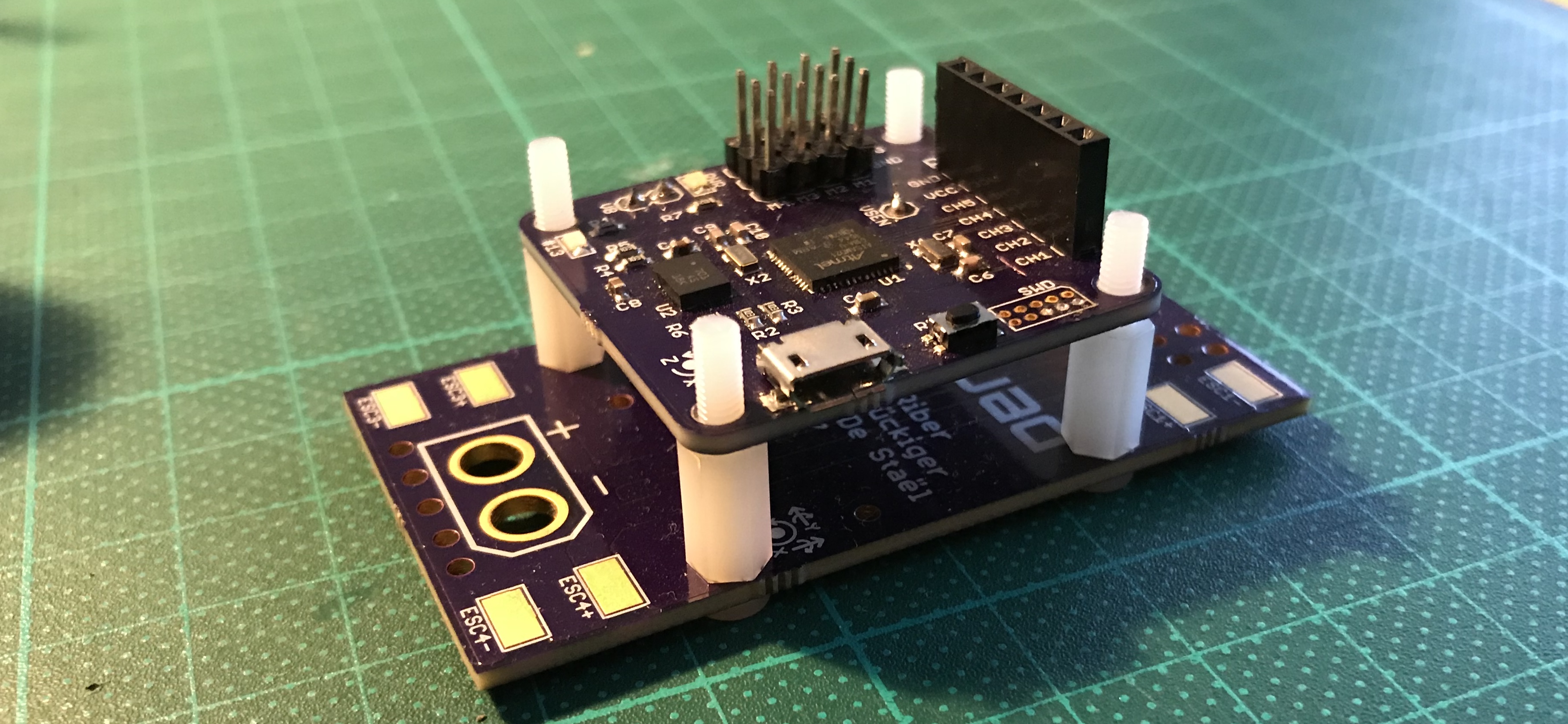
In parallel, I designed the PCB while my friend took care of the code. And we ordered the PCBs:
Assembly went without any problems, and the move from Kapton to steel stencils was welcome :

Conclusion
Tuning the PID controllers proved to be very complex with only our basic understanding, and although we were unable to have the complete quadcopter flying, we were able to validate it on one axis, and were quite happy with the result and learned a lot through this year-long project.
The full report in french can be found below:
